


J-Link ElectronicsAutomotive Electronics Li Jun: Key Technology Research and Application of SiC Power Modules
Release time: 2023-11-08
Source: New energy in the NE era

What can silicon carbide do, including changes in volume, weight, and efficiency, and what practical benefits does it bring? It's cheap and good, so let's talk about cost-effectiveness. What we need to do now is to defeat European and American manufacturers. Don't roll it yourself, roll it out, "said Li Jun, Deputy General Manager of Hefei J-Link Automotive Electronics Co.,Ltd.
In the car, power is the core, and the core power comes from electric drive, which in turn comes from the power module. There is not much difference between silicon carbide and silicon in essence, but the current crystallization technology of silicon carbide results in a relatively low yield, so the cost of silicon carbide is still relatively high. Silicon carbide health management is mainly managed through two methods: active and passive. We take the initiative to do thermal management, while passively we monitor its various voltage and current signals.
J-Link Electronics has applied two 800V silicon carbide electric drive assemblies on silicon carbide modules, one with a power of 250 kW and the other with a power of 200 kW, both with a speed of 20000 rpm and designed according to functional safety. We have completed the entire automotive power electronics conversion, including MCU, OBC, DCDC, and DCAC. We have also conducted research on silicon carbide packaging technology, including single-sided water cooling, double-sided water cooling, and HPD packaging.
The following is a transcript of the speech.
Li Jun: Good afternoon, industry experts. Today, on behalf of J-Link Electronics, I will bring you a topic discussion about "Research and Application of Key Technologies for Silicon Carbide Power Modules". My speech today will mainly focus on three aspects. Firstly, the key technology of silicon carbide modules. Secondly, health management of silicon carbide. Thirdly, what work has J-Link Electronics done in the application of silicon carbide modules.
Recently, everyone knows that the topic of silicon carbide is very popular. US President Biden has regarded silicon carbide materials as a strategic resource for the China US game, and we must also be prepared for combat. Everyone is well aware of this key technology. In the car, power is the core, and the core power comes from electric drive, which in turn comes from the power module. What can silicon carbide do, including changes in volume, weight, and efficiency, and what practical benefits does it bring? It's just cheap and good, let's talk about cost-effectiveness. What we need to do now is defeat European and American manufacturers. Many studies have been conducted in the domestic research and academic circles, and some of the data is the result of our own research. Its key technology is not much different from the original silicon material, and the things it does from raw materials to module manufacturing and finally packaging are basically the same. There is not much difference in the nature of raw materials, but the yield caused by the current crystallization technology of silicon carbide is not particularly high, so the cost of silicon carbide is still relatively high.
Although silicon carbide has been mentioned for many years, we developed a prototype ten years ago. At that time, the price of silicon carbide was 14 times that of silicon material. We made a prototype and studied it, but ultimately did not succeed. In addition to its own yield issue, another problem is that no one has fully understood silicon carbide, mainly because this material is different from silicon-based materials.
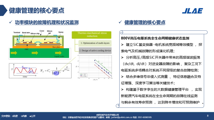
This is a model of IGBT, and we have transplanted it to silicon carbide to study its health management. One principle is that the lifespan of silicon carbide materials is closely related to the maximum junction temperature and temperature fluctuations. The temperature fluctuation and lifecycle of the table in the middle are exponentially related, and the left graph is also very clear. This is a lifecycle model.
What work have we done? Firstly, establish a mechanism model for silicon carbide, which is different from silicon-based materials. Secondly, take out its model. The benefits brought by silicon carbide are mainly high frequency, but everything is double-sided, and the results of high frequency may bring electromagnetic interference. DV/DT and DI/DT are relatively high. We measure the characteristic values of multidimensional signals, and the selection of characteristic values is also a key focus of technical research. Finally, we construct a big data health management platform based on digital twins to achieve online control and prediction of the lifecycle. Throughout the entire process of change, the heart of the car is the power unit, powered by the electric drive, and the heart of the electric drive is the power electronic converter. The core of the power electronic converter lies in these devices. Through fault analysis, it is found that semiconductor devices are the source of its faults, and these sources are mainly accidental and random. To address this phenomenon, we need to study the faults and lifecycle of silicon carbide devices, and what measures we need to use to intervene in them.
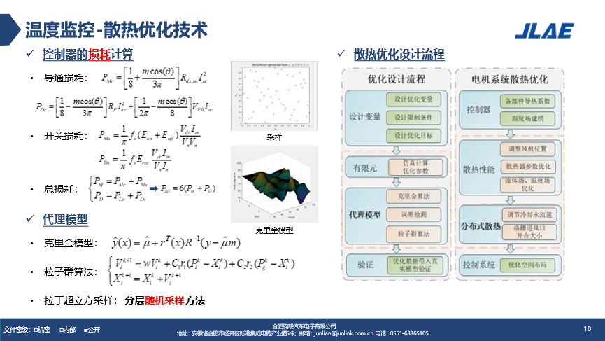
For people, we now have active fitness and passive medication methods, and chips also have active and passive methods. We take the initiative to do thermal management, while passively we monitor its various voltage and current signals to see if it is healthy and how long it can survive. The main losses of the controller are conduction loss and switching loss, and the total loss is this because it is a packaged module. When optimizing the heat dissipation design, these variables are inputted, and the parameters are obtained through finite element analysis. Then, using the Kriging algorithm, we input the optimized data into the experimental model for processing, and we optimize the entire system. On the right side is the process of optimizing the heat dissipation of the entire motor and electronic control system.
We just talked about heat, why monitor temperature? In fact, the most fragile part of our module is the bonding wire. What makes this bonding wire fragile?
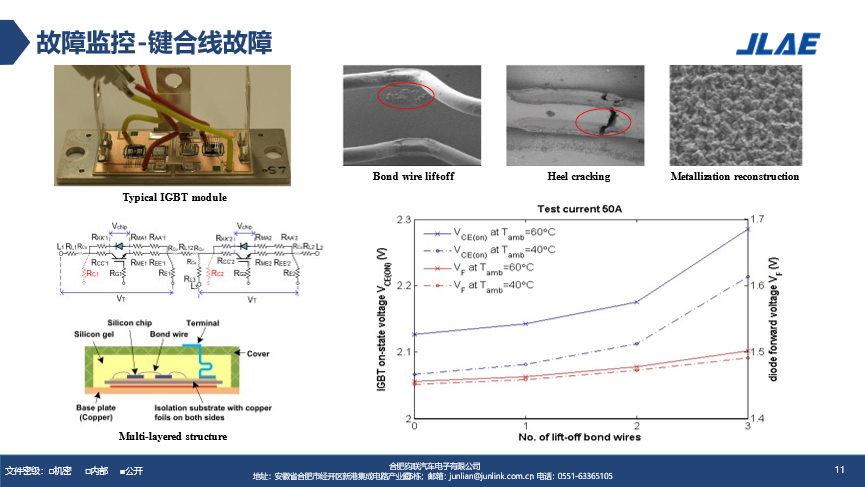
It's because the temperature fluctuates repeatedly. Those who make modules know that these materials are different, and their repeated thermal expansion rates are different. We need to monitor its bonding wire, which is a passive method, while what we just talked about is an active thermal management method. There are several faults in passive mode, one is that the binding wire falls off, and the lead wire breaks. What mechanism do we use to obtain this? The fundamental principle of this method is to collect temperature sensitivity coefficients such as resistance and voltage. The module on the left is a half bridge module, which is a model of IGBT. The same applies to silicon carbide. It's just that its pressure drop and other parameters are slightly different, the principle is the same. We have obtained all its parasitic parameters and detected its voltage on both sides. We can see that if a point falls off at the binding line, the voltage will be slightly higher. The curve is different at each temperature. Finally, we can monitor the change in voltage, obtain the number of points where the binding line falls off, and then know the degree of damage and evaluate whether it should be repaired. The second method is to detect the solder layer. Nowadays, some silicon carbide is sintered with silver, which is a popular process for IGBT.
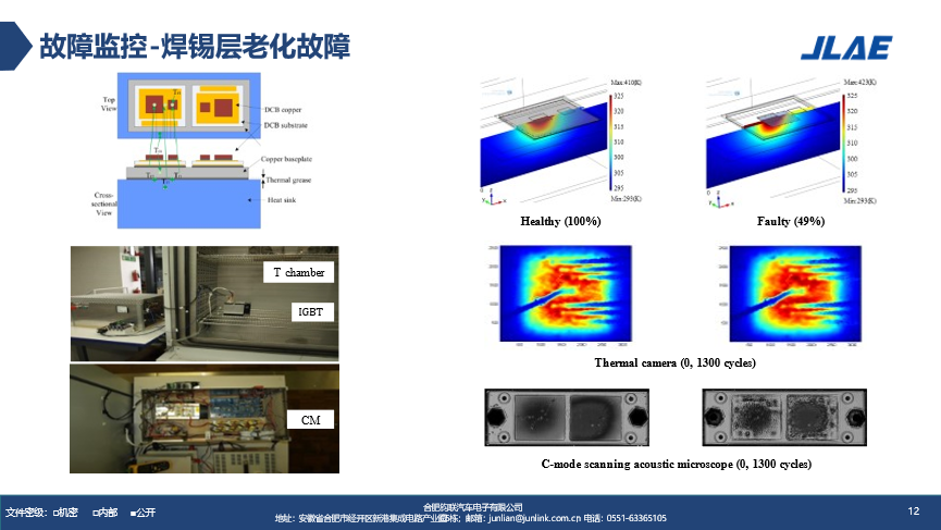
Here is its model above, and below is the testing tool. After 1300 cycles, the healthy results can be seen to be complete at the back. In about half of the damaged cases, this is the case, and solder aging is visible. The intermediate process involves 1300 cycles, with some solder hotspots occurring more frequently than others. This is the offline method we used when we identified some issues, and we have already removed the module from the system.
The above processing methods are all monitoring. In order to solve these problems, we use technical means to monitor the entire module.
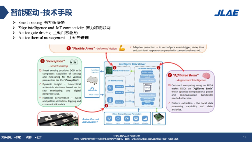
These technological means include installing intelligent sensors and leveraging powerful MCU computing power. We use FPGA to do it, but some people may question whether you can use Infineon chips for calculation? it's fine too. After taking some proactive thermal management measures, the remaining task is to perform some processing on the gate drive, taking into account environmental factors such as humidity, light, pressure, magnetic force, and vibration. Finally, we will develop a driving solution that is more effective than the previous one. Another method is to conduct real-time online evaluation of this device. The original loss model was the cumulative result of the product of current and ESR. The establishment of this model is based on its thermal resistance and loss product plus the ambient temperature. This is a conventional model that many engineers can calculate and directly derive from the data manual. But there is a problem, this is all normal, you can obtain stable values, dynamic ones are not easy to evaluate, and the cumulative results are not like this. Where are the differences in cumulative results reflected? One is that ESR will change, as can be seen from the middle graph, ESR will accumulate over a long period of time and increase. We need to improve its lifespan model, which should be related to the previous thermal models, showing an exponential relationship.
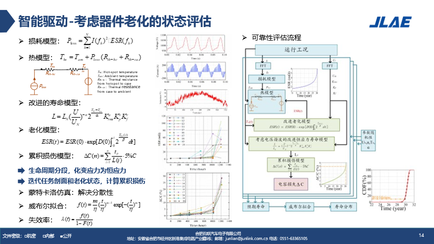
In addition, its damage is the result of cumulative damage, not a constant result over a certain period of time. When engineers choose devices, they usually have a habit of using a constant module, such as 600A, for 500A. At this time, we calculate its loss, which is actually inaccurate because it is constantly changing. We need to improve it. The result of the improvement is to convert variable stress into constant stress throughout the entire lifecycle. We can see its curve from the results of probability statistics.
The curve graph is obtained through Weibull fitting, and at the bottom, we can see the latter half of a power device curve. After fitting, the curve looks like this: how many lifetimes can still exist? This is a means. Silicon carbide high-frequency switches can also bring many problems, such as crosstalk, which can cause some issues. We adjust the main power circuit through other means, such as segmented driving and variable resistance driving. These driving chips include many technological research achievements, such as changing the gate driving resistance. We can achieve it by only dividing it into 2-3 segments, which may not necessarily require so many. The process of oscillation is well known to everyone, and it is precisely because of its small parasitic parameters that we can switch at high frequencies. However, its oscillation during high-frequency switching can affect its lifespan.
The entire intelligent drive adopts a multi information fusion health management concept, which involves data collection, status monitoring, health assessment, and fault prediction, which is provided to maintenance engineers or other after-sales departments. Whether we need to replace this module or wait until the end of its lifespan is like knowing that someone is leaving, we should be prepared. How did we obtain this data? Through human-machine interface and other system interfaces, we have embedded this system into the controller developed by J-Link Electronics. This data can be downloaded offline or exported online through CAN interface.
On this basis, we further investigate and have already involved the reliability of the entire drive system. At this point, we will use some popular techniques, such as convolutional neural networks, digital encoding, and other neural network methods. Detect motor faults and other malfunctions through a giant magnetic detection method. This is a testing platform for motors. On this platform, we process the leakage magnetic signal through Fourier transform to obtain data, and then extract parameters and feature values through convolutional neural network methods. We train the model to predict the current fault and the extent of damage. Another technical approach is to use multi physics field simulation. On the left is to use MATLAB, which is a system level method. The input current and voltage parameters depend on MATLAB and Pspice, reaching the module level. The top is the switch loss, and the bottom is the conduction loss. Finally, a three-dimensional thermal model at the chip level is obtained.
Another approach is that many engineers have various simulation tools, ranging from multi physics fields to single board level, system level, and chip level. Some people feel that the simulation is not accurate, but there is a problem because there is no closed loop. Imitation is imitation, but there is no closed loop. Many structural engineers have experience, so when we simulate it, there is a significant difference between the estimated heat and the actual measured temperature. Why? There is no closed loop. The repeated results of theory to practice and practice to theory are the key to making our simulations more precise and practical. The silicon carbide model on the left is processed using a neural network, which is repeatedly combined with MATLAB and Pspice to form a closed-loop process. This operating condition input can be obtained using Pspice to access the IGBT dynamic database, and then we repeatedly close the loop to obtain a result that is close to reality. It's difficult to be completely accurate. For example, when this model is used for electromagnetic simulation, it's not as accurate in the high frequency range because the parameters change and simulation needs to be combined with reality.

What work has J-Link Electronics done in the application of silicon carbide modules? We have made two 800V silicon carbide electric drive assemblies, one with a power of 250 kW and the other with a power of 200 kW, both with a speed of 20000 rpm and designed according to functional safety. We also made a single electronic control, which weighs only 7.5 kilograms. The whole J-Link Electronics has been around for four or five years now, and we have done a lot of work in this area. We have completed the entire automotive power electronics conversion, including MCU, OBC, DCDC, and DCAC. We have also developed silicon carbide packaging technology, single-sided water cooling, double-sided water cooling, and HPD models.
That's all for my report today, thank you.